
Part 4 - Form Fitting Insole
...Continued from Part 3 - Variable Density Insole
Now it gets interesting. This post concentrates on the scanned data and image manipulation using Gimp, Inkscape and OpenSCAD, all of which are free and open source. However if further refinement of the 3D formed surface is required then Meshmixer is a great free tool (not opensource) for smoothing or twisting and pushing/pulling the mesh around.
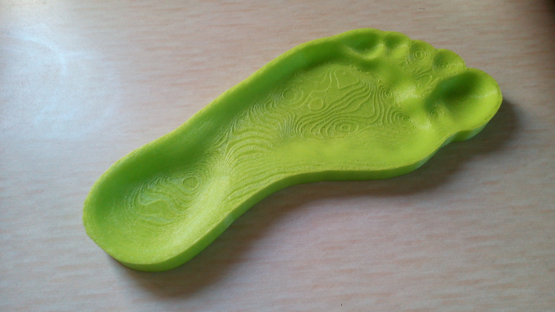
I will show how to scan your foot and turn this into the CAD data used in the previous variable density insole to define the density zones, and also to create the surface data to fit the form of the sole of your foot. The form fitting surface is actually the easy part due to the new great import option in OpenSCAD which build a height map according to the brightness values in an imported digital photo. With a foot scanned on a simple document scanner the areas of the foot that are close to the scanning head, the brighter the image. The areas that are further away are darker. When the surface is built, the darker areas are thicker and the lighter areas are thinner, making a surface as shown :
Now it gets interesting. This post concentrates on the scanned data and image manipulation using Gimp, Inkscape and OpenSCAD, all of which are free and open source. However if further refinement of the 3D formed surface is required then Meshmixer is a great free tool (not opensource) for smoothing or twisting and pushing/pulling the mesh around.
I will show how to scan your foot and turn this into the CAD data used in the previous variable density insole to define the density zones, and also to create the surface data to fit the form of the sole of your foot. The form fitting surface is actually the easy part due to the new great import option in OpenSCAD which build a height map according to the brightness values in an imported digital photo. With a foot scanned on a simple document scanner the areas of the foot that are close to the scanning head, the brighter the image. The areas that are further away are darker. When the surface is built, the darker areas are thicker and the lighter areas are thinner, making a surface as shown :
Form Fitting Insole
 RSS Feed
