
Part 3 - Variable Density Insole
...Continued from Part 2 - Open Core Mesh
It is now where we start to see a major advantage of 3D printing over existing insole technology. The traditional method to make a custom formed insole is to CNC machine the insole out of a solid block of a suitable chosen hardness of material. Post machining modifications can be implemented by added inserts in different materials etc. Any operation that requires multiple steps is adding to the complexity, inventory of different material stocks, skills and of course cost.
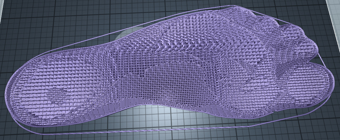
Here we can see that for a single use of material and machine (3D printer), a complex structure of insole can be created with differing grades of hardness according to the recipients needs.
It is now where we start to see a major advantage of 3D printing over existing insole technology. The traditional method to make a custom formed insole is to CNC machine the insole out of a solid block of a suitable chosen hardness of material. Post machining modifications can be implemented by added inserts in different materials etc. Any operation that requires multiple steps is adding to the complexity, inventory of different material stocks, skills and of course cost.
Here we can see that for a single use of material and machine (3D printer), a complex structure of insole can be created with differing grades of hardness according to the recipients needs.
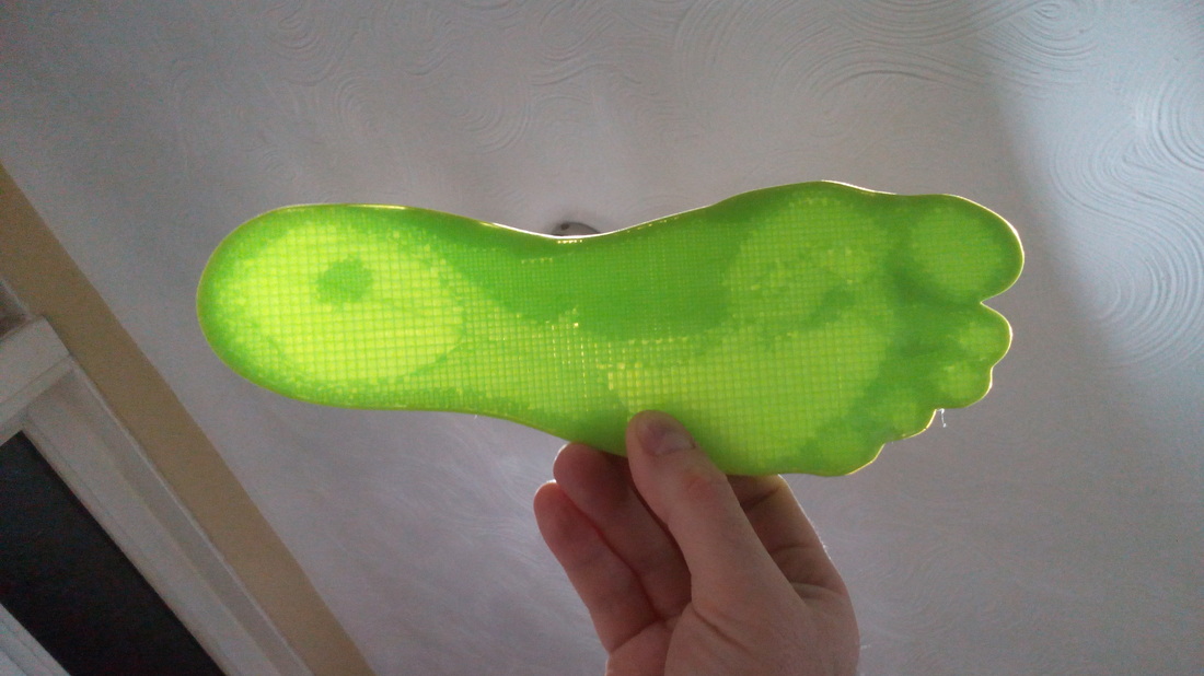
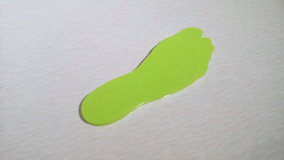
Insole consisting of firm and soft areas
This model was created using a scan of a recipients foot, the whole scanning and modelling procedure will be detailed in the next blog post.
The example above is a completely uniform 10mm thick for no other reason than to show you when holding it up to the light, you can see the variation of the density without any thickness changes distorting the light pattern.
The example above is a completely uniform 10mm thick for no other reason than to show you when holding it up to the light, you can see the variation of the density without any thickness changes distorting the light pattern.
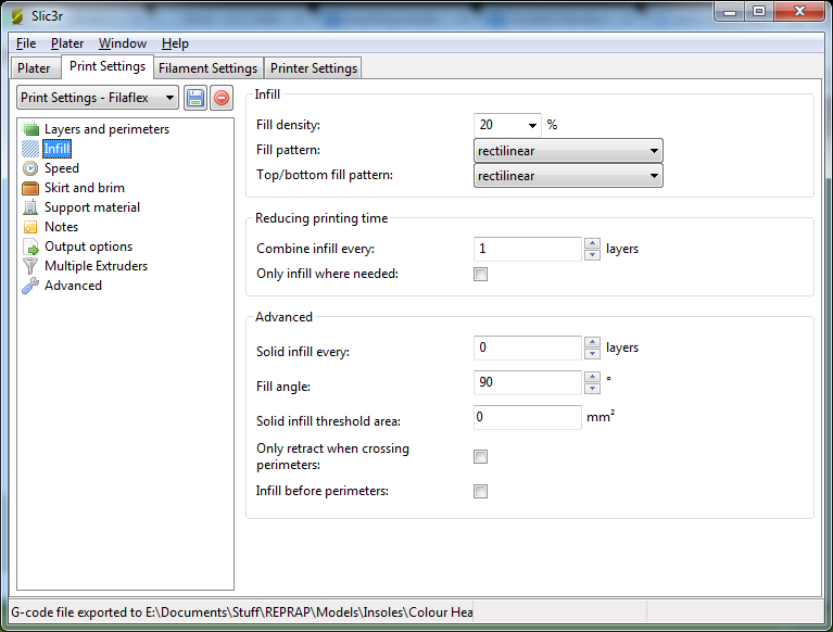
I printed out some sample parts to try out the various infill percentages, both with top/btm surfaces and open core variants described in my previous post. These are great to squeeze in the hand to get a feel for the softness and flexibility of the material.
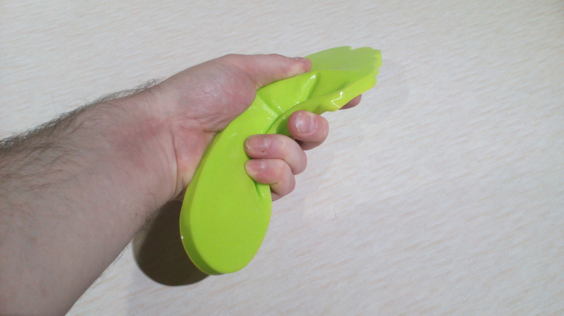
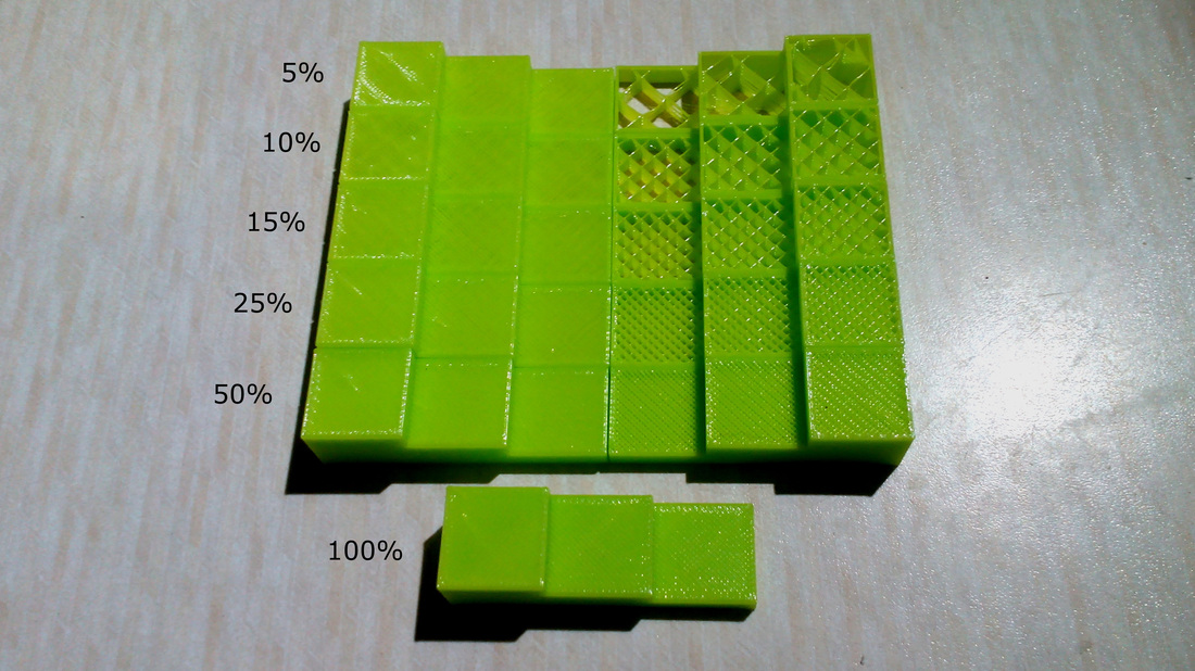
Various infill percentages
One of the newer features in Slic3r is "Modifier Meshes", a great example where and how they can be used can be found on the original Slic3r blog. Please read this first to let yourself in gently.
My example stl files and Slic3r setting files can be downloaded from Thingiverse.
Note : Slic3r version used 1.1.7
If you import my Config Bundle and .amf file (Additive Manufacturing File) into Slic3r then the following settings are defined for you, allowing you to export gcode straight away.
My example stl files and Slic3r setting files can be downloaded from Thingiverse.
Note : Slic3r version used 1.1.7
If you import my Config Bundle and .amf file (Additive Manufacturing File) into Slic3r then the following settings are defined for you, allowing you to export gcode straight away.
How to Programme Variable Densities in Slic3r
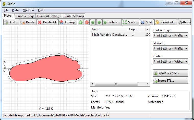


Export G-code as normal from the button on panel 1. As a backup, it is best to export your config bundle and .amf files so you can save your slicing settings for another session.
If all goes well, you should have some G-code that you can print with, you can check mine out here.
If all goes well, you should have some G-code that you can print with, you can check mine out here.
Variable Density G-code
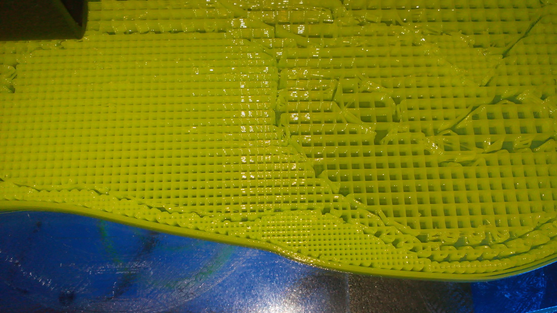
Halfway through the print
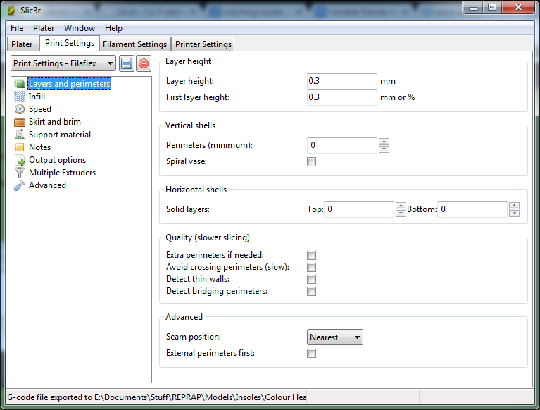
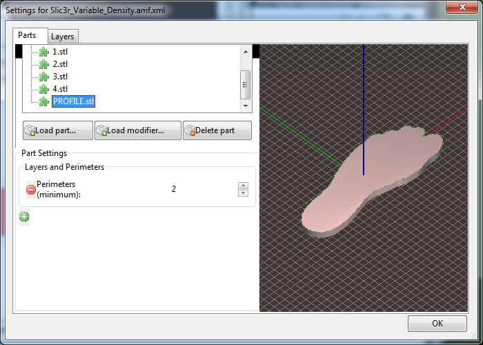
It's important not to have any perimeters around these "Density Zones" otherwise this will create contours which will be firmer than the surrounding infill and could lead to discomfort. For this reason, perimeters were switched off in stage 2, however we still need some perimeters around the whole insole, so this is the reason for adding a PROFILE.stl in stage 8.
If you would like to have a practice at printing some variable density insoles, and messing around with the values then download the examples from my Thingiverse page.
So far, I have purposely stayed away from the techniques and procedures involved in the image and CAD side for simplicity until the next article. The free opensource tool chain used will be Gimp, Inkscape and finally OpenSCAD to create the CAD models. The result will offer "Form Fitting" variant too.
The disclaimer here is that I am only providing information, this is not medically certified and is not designed to be such, but hey in many parts of the world, people walk round on planks of wood or old car tyres so everything is builder beware. Go forth and MAKE!!!
 RSS Feed
