
Part 4 - Form Fitting Insole
...Continued from Part 3 - Variable Density Insole
Now it gets interesting. This post concentrates on the scanned data and image manipulation using Gimp, Inkscape and OpenSCAD, all of which are free and open source. However if further refinement of the 3D formed surface is required then Meshmixer is a great free tool (not opensource) for smoothing or twisting and pushing/pulling the mesh around.
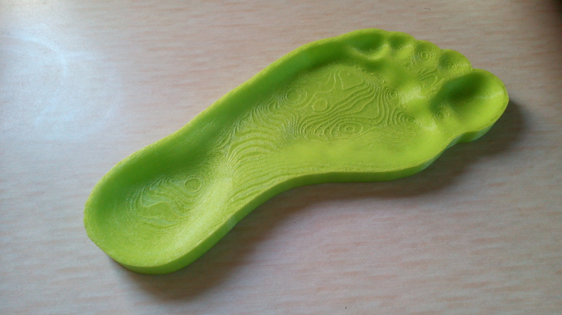
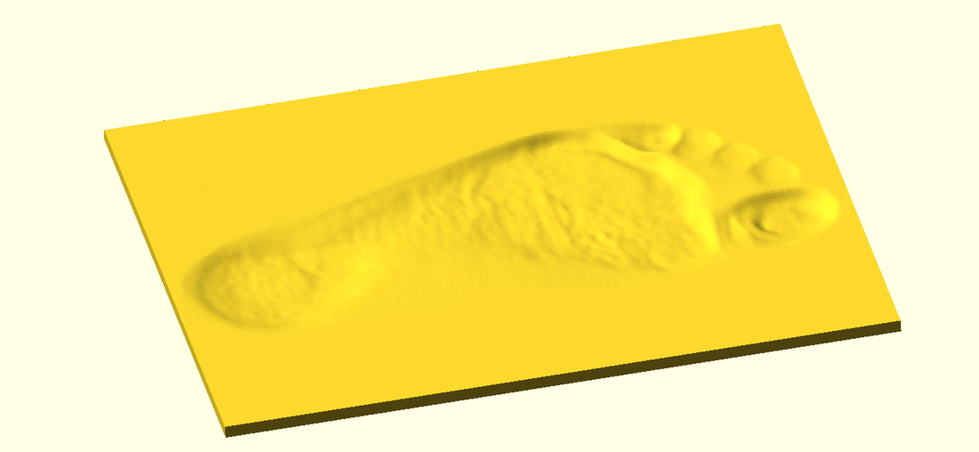
I will show how to scan your foot and turn this into the CAD data used in the previous variable density insole to define the density zones, and also to create the surface data to fit the form of the sole of your foot. The form fitting surface is actually the easy part due to the new great import option in OpenSCAD which build a height map according to the brightness values in an imported digital photo. With a foot scanned on a simple document scanner the areas of the foot that are close to the scanning head, the brighter the image. The areas that are further away are darker. When the surface is built, the darker areas are thicker and the lighter areas are thinner, making a surface as shown :
Now it gets interesting. This post concentrates on the scanned data and image manipulation using Gimp, Inkscape and OpenSCAD, all of which are free and open source. However if further refinement of the 3D formed surface is required then Meshmixer is a great free tool (not opensource) for smoothing or twisting and pushing/pulling the mesh around.
I will show how to scan your foot and turn this into the CAD data used in the previous variable density insole to define the density zones, and also to create the surface data to fit the form of the sole of your foot. The form fitting surface is actually the easy part due to the new great import option in OpenSCAD which build a height map according to the brightness values in an imported digital photo. With a foot scanned on a simple document scanner the areas of the foot that are close to the scanning head, the brighter the image. The areas that are further away are darker. When the surface is built, the darker areas are thicker and the lighter areas are thinner, making a surface as shown :
Form Fitting Insole
Form Fitting Process
Step 1 - Scan the Foot
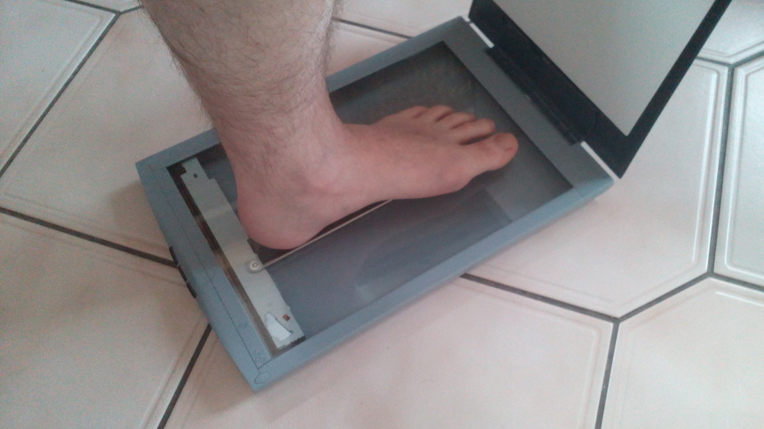
Capture foot with a flat-bed document scanner (A4 or A3).
IMPORTANT 1 : For image quality and safety, TRY NOT TO PUT PRESSURE ON SCANNER.
IMPORTANT 2 : Scan the foot in a dark room at night so the background of the scanned image is black.
Capture foot with a flat-bed document scanner (A4 or A3).
IMPORTANT 1 : For image quality and safety, TRY NOT TO PUT PRESSURE ON SCANNER.
IMPORTANT 2 : Scan the foot in a dark room at night so the background of the scanned image is black.
Warning - HOBBIT foot alert
Step 2 - Manipulate the Image
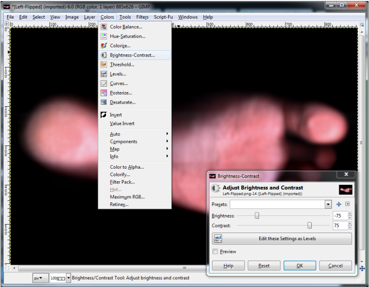
Depending on the quality of the scanner and image it maybe necessary in Gimp to modify the Brightness (-75) and Contrast (+75). The idea is to try and achieve a dark background with the foot fading away into the distance, so experiment with the values somewhat.
Depending on the quality of the scanner and image it maybe necessary in Gimp to modify the Brightness (-75) and Contrast (+75). The idea is to try and achieve a dark background with the foot fading away into the distance, so experiment with the values somewhat.
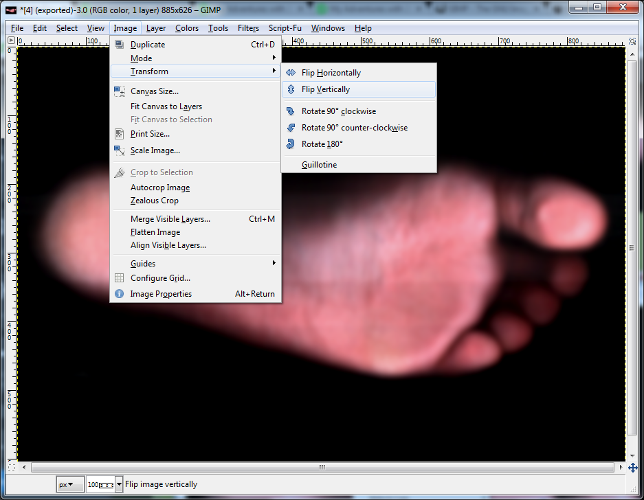
Flip the image vertically, otherwise the finished insole will end up for the opposite foot.
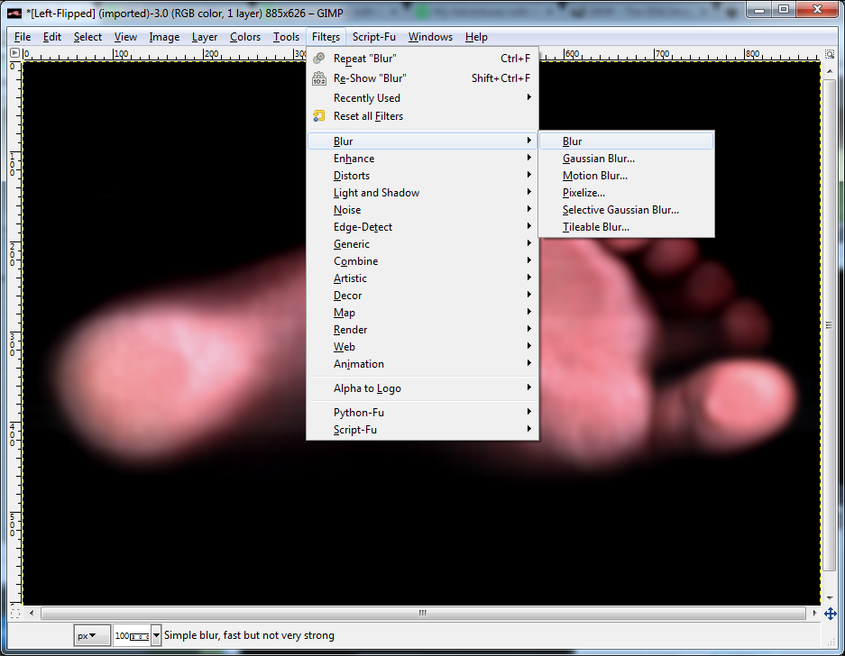
Blur the image about 5 times in Gimp to make it have a "soft focus" effect.
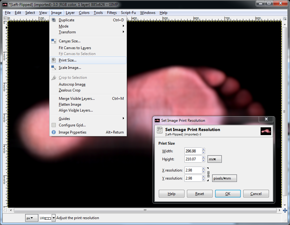
Check the scale of the scanned image in Gimp and adjust if necessary. If you have an A4 scanned image make sure the Print Size is set to mm and the Width and Height are set to 297mm x 210mm resp.
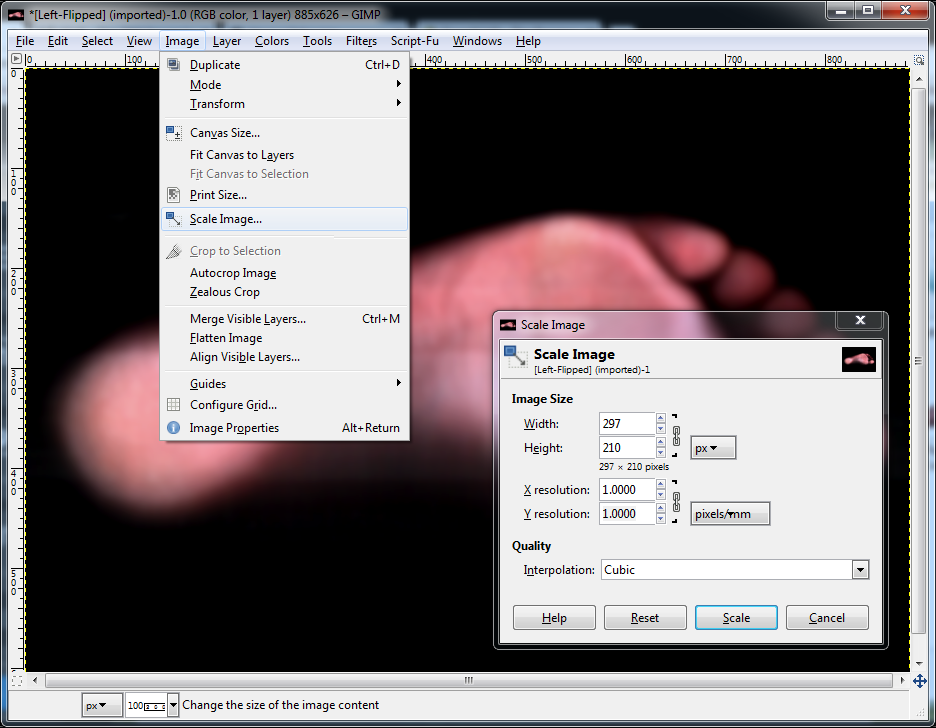
It is most probable that the scanned resolution of the image is far too high for OpenSCAD to render quickly. One pixel of image will equal 1 unit of measurement in OpenSCAD (usually 1mm). If we have a high resolution scan then the resultant model will be both large in spacial terms as well as file storage and memory usage. Therefore we need to export out of GIMP a smaller less detailed image of the scan just for the surface form.
Scale the image so that the Width and Height = 297px x 210px and the X Y resolution is set to 1 px/mm each.
Scale the image so that the Width and Height = 297px x 210px and the X Y resolution is set to 1 px/mm each.
File then Export as a Scanned_Foot_Filename.png file, where "Scanned_Foot_Filename" is your choice, but we will refer to this filename later.
Step 3 - Creating the Surface in OpenSCAD
At the time of writing, the released version of OpenSCAD (2014.03) does not contain the latest command that is required for the surface creation and also the Offset command that we will touch on later. I downloaded a development snapshot of OpenSCAD, Version 2014.12.04. I guess any of the later versions will equally work.
This simple OpenSCAD code will create a surface solid, replace "Scanned_Foot_Filename" with the name of the scaled down file you created in the previous step :
scale([1, 1, 0.15])
surface(file = "Scanned_Foot_Filename.png", center = false, invert = true);

We need to crop this block to the profile of the foot from the scan. It is now where we can manipulate the image further. This will enable us to define the zones which we will also use in the previous Variable Density Insole post and also to create the profiling solid (often called a "cookie cutter") for this surface block.
I will therefore take a backwards move and re-visit a little more image manipulation in GIMP and the extra work in Inkscape for the Variable Density Meshes.
I will therefore take a backwards move and re-visit a little more image manipulation in GIMP and the extra work in Inkscape for the Variable Density Meshes.
Variable Density Process
Step 1 - Artistic Cutout in GIMP
To achieve nice smooth zones, we start with the higher resolution blurred image in GIMP from the previous steps.
The great part of opensource is that many talented people all contribute to making the software better in one form or another. In the case of GIMP there are many plugins/extensions/scripts that are user created that offer extra effects that are not packaged within the original distribution of the released GIMP. There is an "Artistic Cutout" script that modifies the original image to a reduced number of colours and zones them off.
The Artistic Cutout script (originally by Eddy Verlinden) can be downloaded from here. It's a case of saving the script into the GIMP scripts installation folder so it can be used, more info here.
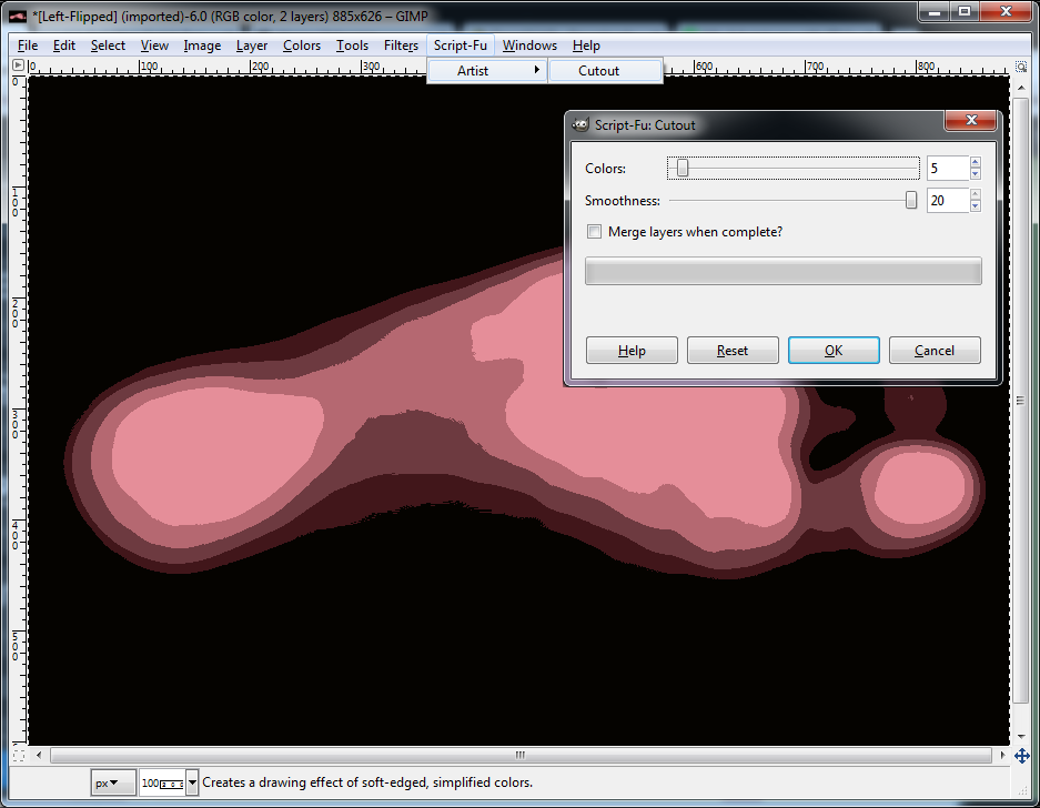
Once the script is available in GIMP choose the amount of zones (colours) you wish to print, try about 5 or 6, Note, the background black will be one of the zones, but like in this instance it could form one of the internal zones too (around the toes).
To achieve nice smooth zones, we start with the higher resolution blurred image in GIMP from the previous steps.
The great part of opensource is that many talented people all contribute to making the software better in one form or another. In the case of GIMP there are many plugins/extensions/scripts that are user created that offer extra effects that are not packaged within the original distribution of the released GIMP. There is an "Artistic Cutout" script that modifies the original image to a reduced number of colours and zones them off.
The Artistic Cutout script (originally by Eddy Verlinden) can be downloaded from here. It's a case of saving the script into the GIMP scripts installation folder so it can be used, more info here.
Once the script is available in GIMP choose the amount of zones (colours) you wish to print, try about 5 or 6, Note, the background black will be one of the zones, but like in this instance it could form one of the internal zones too (around the toes).
Open up the Toolbox (Ctrl+B) and Flood fill the background to turn it white.
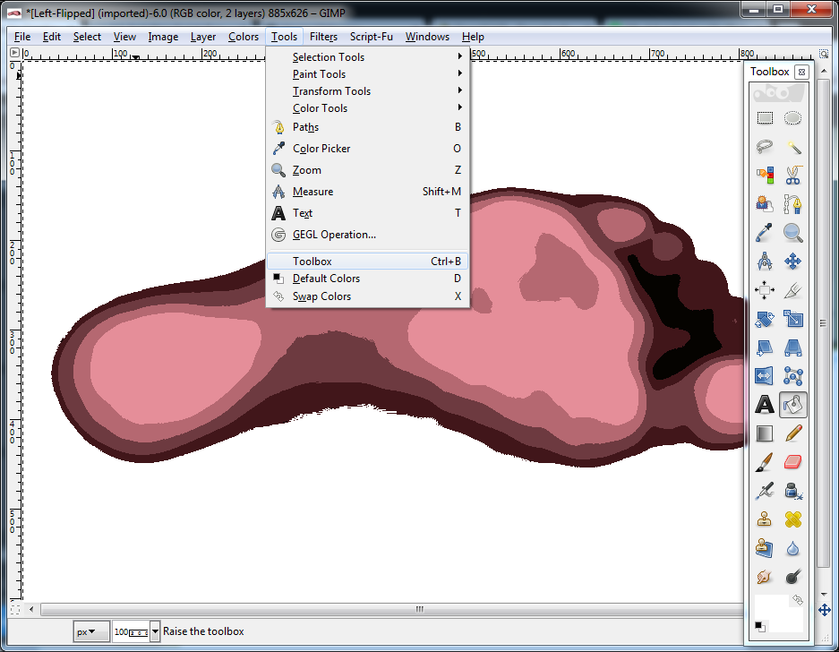
This is the stage to make any minor tweaks or adjustments. Use the dropper to select a source zone colour of your choice then paint out any areas not required or smooth some boundaries, or just leave as is.
Export the image as a .bmp for importing into Inkscape.
Step 2 - Creating the Vector profiles in Inkscape
The image so far looks like it is suitably zoned but the data needs to be turned into profile curves and ultimately STL 3D data for slicing in our 3D printing programme. For this we import the previous exported .bmp file into the vector graphics editor Inkscape. At the time of writing I used Inkscape 0.48.5.
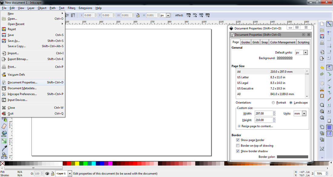
Open up Inkscape and set the document size to A4 Landscape and mm units, same size as the scanned image:
Export the image as a .bmp for importing into Inkscape.
Step 2 - Creating the Vector profiles in Inkscape
The image so far looks like it is suitably zoned but the data needs to be turned into profile curves and ultimately STL 3D data for slicing in our 3D printing programme. For this we import the previous exported .bmp file into the vector graphics editor Inkscape. At the time of writing I used Inkscape 0.48.5.
Open up Inkscape and set the document size to A4 Landscape and mm units, same size as the scanned image:
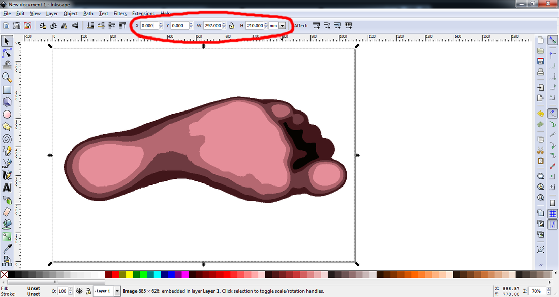
Import the .bmp image and set the size and position of the image to the document boundaries.
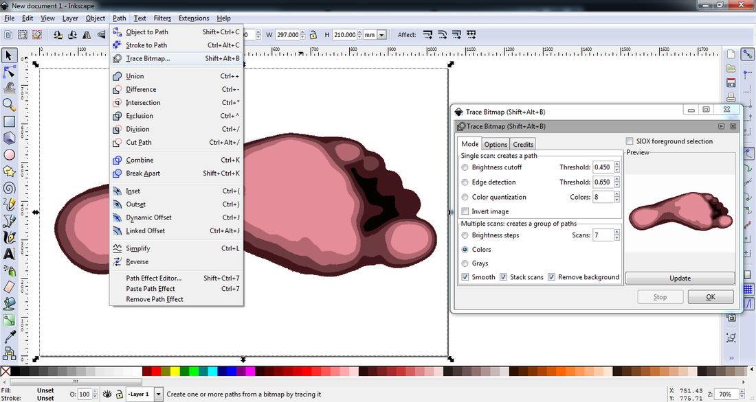
A great feature of Inkscape is that is will trace an imported bmp image and create vectorised zone patches which can then be used to export profile curves for use in a CAD programme such as OpenSCAD.
Set the Dialog box to the following options. You may need to change the number of scans until the preview (click update each time) matches the imported .bmp. Sometimes some zones will disappear if set too low and if set too high, extra zones that are not needed will be created.
Set the Dialog box to the following options. You may need to change the number of scans until the preview (click update each time) matches the imported .bmp. Sometimes some zones will disappear if set too low and if set too high, extra zones that are not needed will be created.
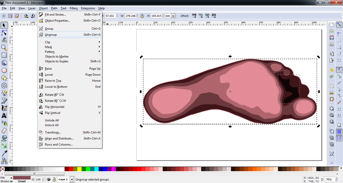
Once the zones are created, they are automatically grouped together, so we need to Ungroup them to separate the paths.
If we zoom in (+ key) there always seems to be an erroneous zone created which we do not need so while we are zoomed in, we can select this and press the delete key to remove.
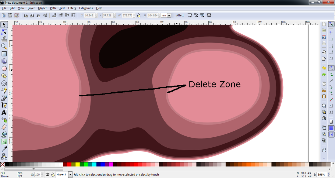 Before |  After |
Do not move the objects, but for example if we were to drag the objects about, you will see that separate zones have been created:
Example exploded view only, do not move the objects.
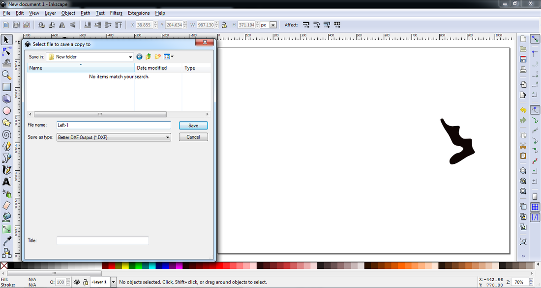
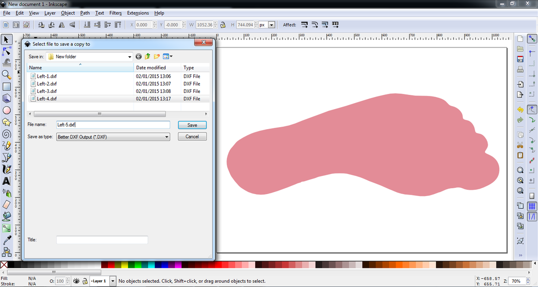
I would recommend that you now save your Inkscape work before we start to export each different object to a separate .dxf file. For this we need another plugin which allows the creation of a DXF file that OpenSCAD can read in (i.e. no splines).
The "better dxf output" plugin by Bob Cook can be downloaded from here. Usually extract the contents of the zip file into the Inkscape extensions installation folder (C:\Program Files\Inkscape\share\extensions\ for Windows). More information on the installation here.
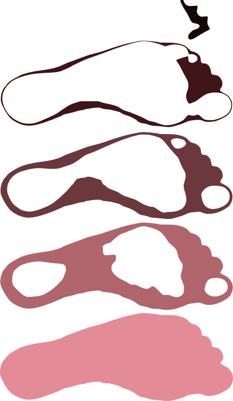
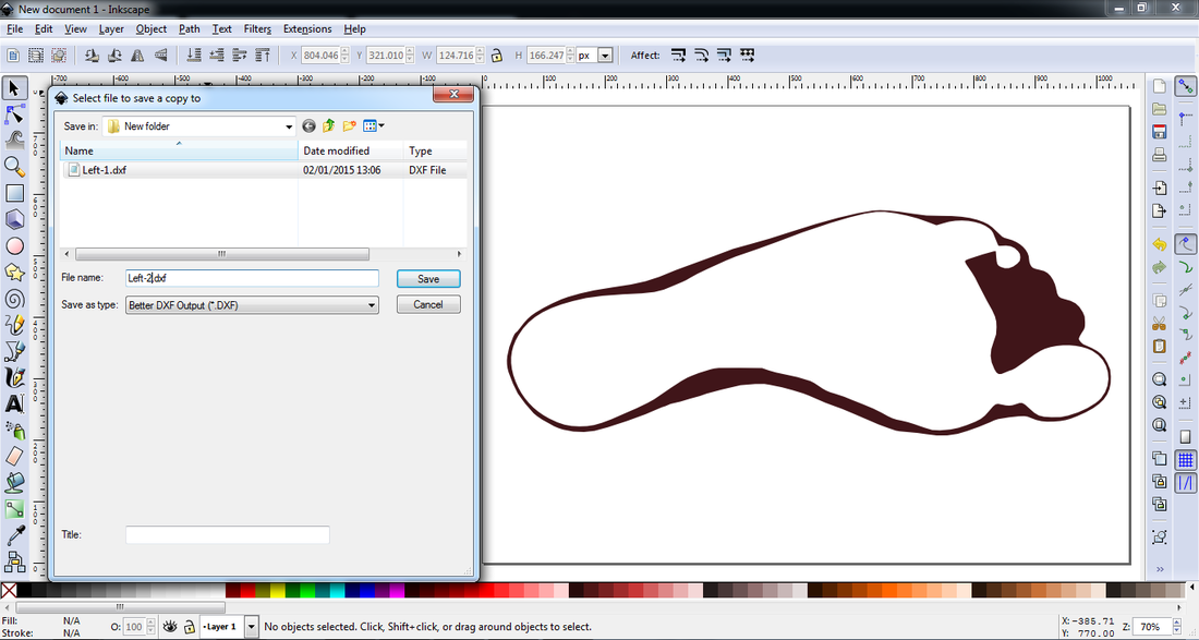
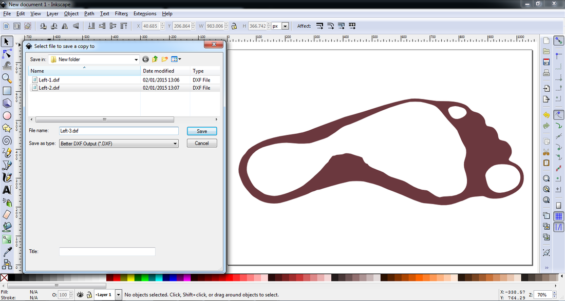
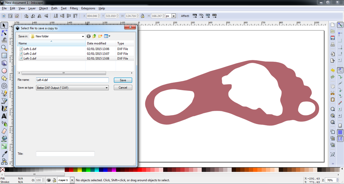
Start by deleting all the objects except for the with the darkest zone, then save a copy of this as Left-1.dxf using the "Better DXF Output" file type option. Undo your deletes (Control+z) and then delete all zones except for the next darkest. Save this as Left-2.dxf, and do the same for all other zones like the following :
The "better dxf output" plugin by Bob Cook can be downloaded from here. Usually extract the contents of the zip file into the Inkscape extensions installation folder (C:\Program Files\Inkscape\share\extensions\ for Windows). More information on the installation here.
Start by deleting all the objects except for the with the darkest zone, then save a copy of this as Left-1.dxf using the "Better DXF Output" file type option. Undo your deletes (Control+z) and then delete all zones except for the next darkest. Save this as Left-2.dxf, and do the same for all other zones like the following :
OpenSCAD Modelling
Form Fitting
Now that all of the profile curve files have been created for each zone, we can import these into OpenSCAD to create 3D stl files for use in our printer slicing programme (Slic3r). We also have a boundary curve (Left-5.dxf) which can be used to profile off the surface form insole that we created earlier in this post.
Now that all of the profile curve files have been created for each zone, we can import these into OpenSCAD to create 3D stl files for use in our printer slicing programme (Slic3r). We also have a boundary curve (Left-5.dxf) which can be used to profile off the surface form insole that we created earlier in this post.
BUG ALERT!
I don't know why this happens but the dxf files that get exported from Inkscape seem to have their co-ordinates shifted by a random amount for each scanned image. It is this reason why the imported profiles and the surface data do not line up. I have therefore include an xoffset and a yoffset parameter which can be modified to align the profile solid over the surface, a bit of trial and error this one by pressing F5 to preview between each iteration of the offset values.
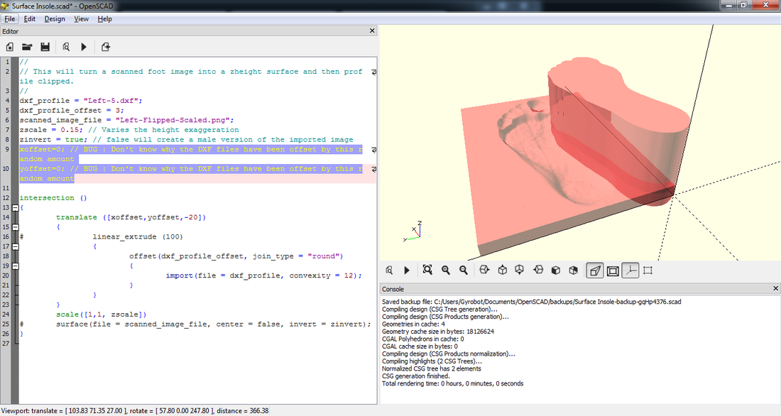
The two "#" at the beginning of the code below turn on the solid visualisation (translucent pink) for that command. When you see the two solids visually intersect then these can be removed to see the complete render.
I don't know why this happens but the dxf files that get exported from Inkscape seem to have their co-ordinates shifted by a random amount for each scanned image. It is this reason why the imported profiles and the surface data do not line up. I have therefore include an xoffset and a yoffset parameter which can be modified to align the profile solid over the surface, a bit of trial and error this one by pressing F5 to preview between each iteration of the offset values.
The two "#" at the beginning of the code below turn on the solid visualisation (translucent pink) for that command. When you see the two solids visually intersect then these can be removed to see the complete render.
Form Fitting OpenSCAD Code
User Variables in Bold
User Variables in Bold
//
// This will turn a scanned foot image into a zheight surface and then profile clipped.
//
dxf_profile = "Left-5.dxf";
dxf_profile_offset = 3;
scanned_image_file = "Scanned_Foot_Filename.png";
zscale = 0.15; // Varies the height exaggeration
zinvert = true; // false will create a male version of the imported image
xoffset=-2; // BUG : Don't know why the DXF files have been offset by this random amount
yoffset=87; // BUG : Don't know why the DXF files have been offset by this random amount
intersection ()
{
translate ([xoffset,yoffset,-20])
{
# linear_extrude (100)
{
offset(dxf_profile_offset, join_type = "round")
{
import(file = dxf_profile, convexity = 12);
}
}
}
scale([1,1, zscale])
# surface(file = scanned_image_file, center = false, invert = zinvert);
}
When you are happy with the alignment and it looks something like the image below, press F6 to perform the Render (slow) and export an STL file. Also remember the X and Y offsets, we will use them in the Variable Density Insole below too.
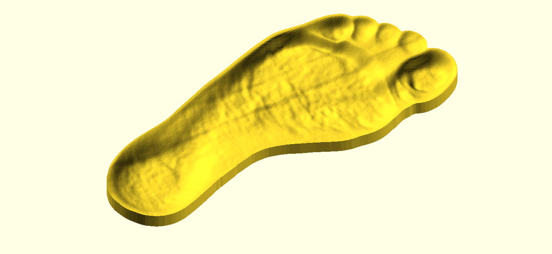
Surface Form insole trimmed with profile curve solid.
Variable Density
The X and Y offsets from above will be used to position the dxf files in this OpenSCAD code too.
Use F5 for a quick preview with colours rendered. This option will vary the height of the solids so that you can see the visible zones. For exporting, the heights of the solid get modified so that they all sit inside the main shell, which is the purpose of the "stl_zoffset" parameter. When you are ready to export the solids, replace the export variable from "none" with the name of the profile you would like to export (e.g. "dxf_file1", "dxf_file2" etc.) then press F6 and export an STL file. Do this for each solid and you are now ready to program these variable density meshes.
Please see my previous blog post on how to programme these STL files.
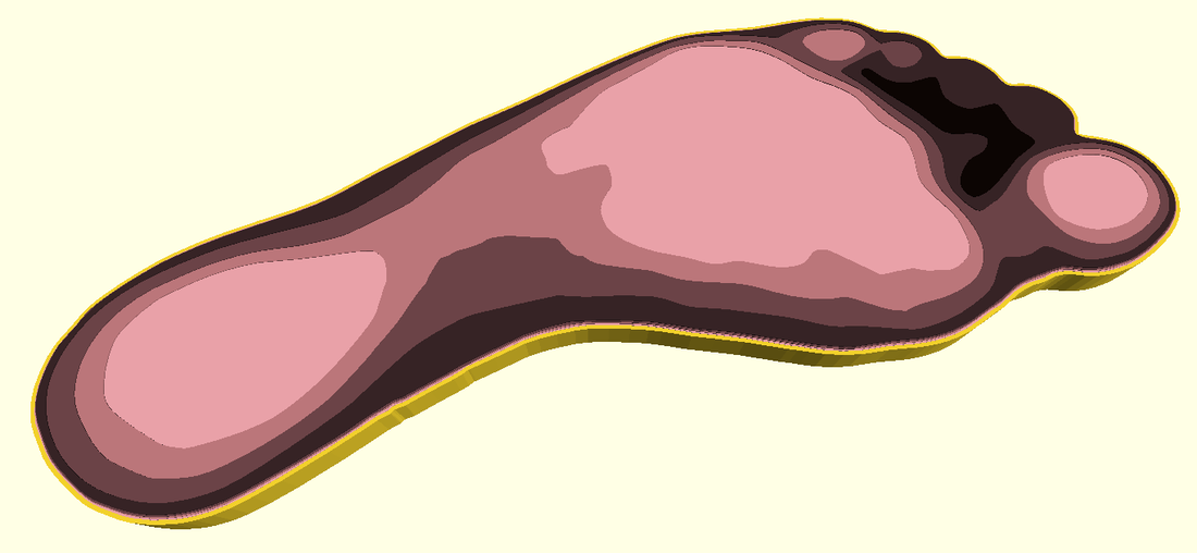
Variable Density Solids created in OpenSCAD
Variable Density OpenSCAD Code
User Variables in Bold
User Variables in Bold
//
// This will create the stls for the Variable Density zones.
//
//
// DXF files in order of Density : Hard = 1st in list.
//
dxf_file1 = "Left-1.dxf";
dxf_file2 = "Left-2.dxf";
dxf_file3 = "Left-3.dxf";
dxf_file4 = "Left-4.dxf";
dxf_file5 = "Left-5.dxf";
dxf_profile = "Left-5.dxf";
export = "none" ; // Set to "none" for F5 Colour visualisation, or "dxf_file[1-5]" above for exporting
export_height = 10 ; // Thickness of Insole Required
//
xoffset=-2; // BUG : Don't know why the DXF files have been offset by this random amount
yoffset=87; // BUG : Don't know why the DXF files have been offset by this random amount
stl_zoffset = 0.7 ; // Z Offset for internal stl profiles to achieve solid top/btm surfaces
profile_thickness = 0.9 ; // Sets thickness of perimeter "dxf_profile"
//
// Main Code
//
ztranslate = export=="none" ? 0 : stl_zoffset;
stl_zextrude = export=="none" ? 0.25 : 0;
translate([xoffset,yoffset,])
{
linear_extrude (export_height-(2*stl_zextrude)-(3*stl_zextrude))
{
offset(delta = profile_thickness, join_type = "round")
{
if (export == "dxf_profile" || export == "none") import(file = dxf_profile, convexity = 12);
}
}
}
translate([xoffset,yoffset,ztranslate])
{
color([0.04705,0.01960,0.01176])
linear_extrude (export_height-(2*stl_zoffset)+(5*stl_zextrude))
{
if (export == "dxf_file1" || export == "none") import(file = dxf_file1, convexity = 12);
}
color([0.2156862745098039,0.1411764705882353,0.1490196078431373])
linear_extrude (export_height-(2*stl_zoffset)+(4*stl_zextrude))
{
if (export == "dxf_file2" || export == "none") import(file = dxf_file2, convexity = 12);
}
color([0.4313725490196078,0.2705882352941176,0.2862745098039216])
linear_extrude (export_height-(2*stl_zoffset)+(3*stl_zextrude))
{
if (export == "dxf_file3" || export == "none") import(file = dxf_file3, convexity = 12);
}
color([0.7529411764705882,0.4745098039215686,0.4901960784313725])
linear_extrude (export_height-(2*stl_zoffset)+(2*stl_zextrude))
{
if (export == "dxf_file4" || export == "none") import(file = dxf_file4, convexity = 12);
}
color([0.9372549019607843,0.6509803921568627,0.6784313725490196])
linear_extrude (export_height-(2*stl_zoffset)+(1*stl_zextrude))
{
if (export == "dxf_file5" || export == "none") import(file = dxf_file5, convexity = 12);
}
}
Final Word
I realise this is a multi stage process and there is a lot of detail within this post, there maybe a way to reduce some of the steps or even somebody out there is dedicated and talented enough to automate some of the steps. I would love to hear improvements, issues advice etc.
Smoothing
One improvement I would like to suggest is to neutralise the natural colour variation of the underside of the foot. For this maybe a neutral coloured sock is preferred or an even coat of none sticky foundation make-up etc. This should help smooth out the Form Fitting surface somewhat and reduce the bumpiness. However I will now show you in Meshmixer (free tool) how it is a simple process to smooth out the insole surface.
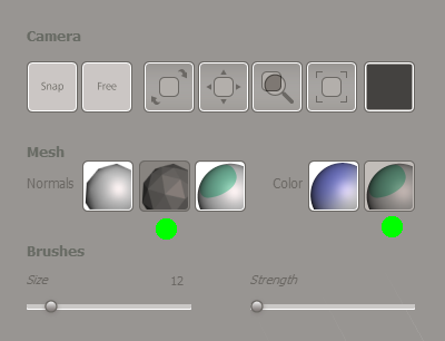
Import the STL mesh into Meshmixer and set the render options with the spacebar (green circles):
Smoothing
One improvement I would like to suggest is to neutralise the natural colour variation of the underside of the foot. For this maybe a neutral coloured sock is preferred or an even coat of none sticky foundation make-up etc. This should help smooth out the Form Fitting surface somewhat and reduce the bumpiness. However I will now show you in Meshmixer (free tool) how it is a simple process to smooth out the insole surface.
Import the STL mesh into Meshmixer and set the render options with the spacebar (green circles):
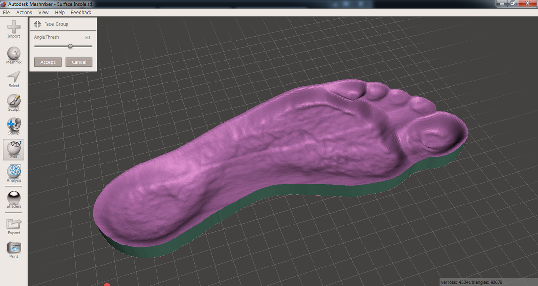
Under the Edit menu, there is a "Generate Face Groups" option. This will help us easily select the upper surface for smoothing without selecting the side walls. Set the "Angle Thresh" to around 50 or similar so the upper surface gets a colour all of its own and then Accept.
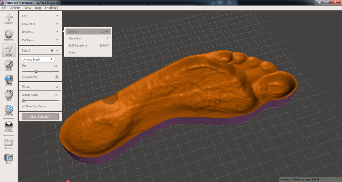
Click the select icon on the left and double click the upper surface to select all of the triangles as a single face group. Once the upper surface turns orange, you can now choose to increase the insole thickness by going into the Deform - Transform menu or straight into the the Deform - Smooth (Control+F) menu (next step). If you choose to increase the thickness, just drag the vertical Z axis handle upwards until desired thickness is achieved.
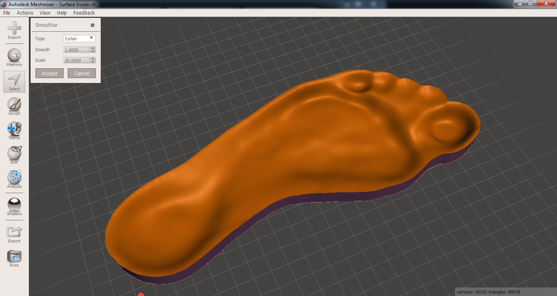
Setting the Scale to around 20 smooths out the ripples. Accept the value that you are happy with and then Export out a new STL file.
You can download this model from Thingiverse, but it is probably useless for you, however now you can go and 3D Print your own insole/sandal/flipflop in Filaflex too.
 RSS Feed
